
HYDROPOWER UNITS
MC-monitoring delivers state-of-the-art monitoring solutions specially designed for hydropower units. Our expertise covers every technology layer — from sensing to protection and condition monitoring, through diagnostics and predictive maintenance — providing complete visibility and reliability for critical rotating machinery.
Designed to meet the evolving challenges of modern power generation, our solutions help operators assess the condition of their hydroelectric machines. Whether you operate a large grid-critical generator or a small run-of-river unit, MC-monitoring ensures the right balance between real-time protection, machine health monitoring, and predictive insights for every hydropower application.
Classification by machine size and monitoring objectives
Our recommended monitoring level depends not only on the machine’s power rating but also on its operational criticality. These recommendations serve as a guideline and can be adapted to specific customer requirements.
Category | Typical Power Range / Criticality | Monitoring Objective |
|---|---|---|
Note: This classification reflects typical hydropower industry practice. Standards such as ISO 20816 and API 670 classify rotating machines primarily by function and criticality rather than fixed power ranges.
Recommendations for Large Hydropower Units (>50 MW or Critical Units)
In large or critical hydropower units, every mechanical component is critical. A single failure can cause extensive downtime and costly damage.
MC-monitoring offers a comprehensive protection and condition monitoring solution specifically engineered for these high-value assets. Our approach combines dedicated sensors installed on key mechanical components with rack-based acquisition systems and condition monitoring software, providing complete visibility of your unit’s health — from the generator to the bearings and turbine runner.
Overall System Description
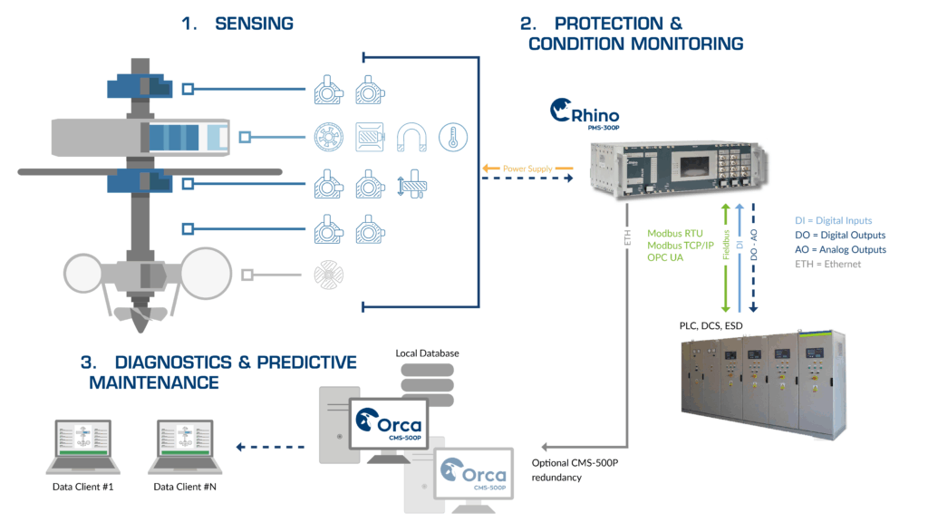
Sensing – MCm sensors
Machine Element: Shaft & Bearings
Monitoring Solution | Sensors | Measurement Parameter | Purpose / Failure Modes Detected |
|---|---|---|---|
 | |||
  |
Machine Element: Generator
Monitoring Solution | Sensors | Measurement Parameter | Purpose / Failure Modes Detected |
|---|---|---|---|
 | |||
 | |||
 | |||
 |
Machine Element: Turbine Runner
Monitoring Solution | Sensors | Measurement Parameter | Purpose / Failure Modes Detected |
|---|---|---|---|
 |
All sensors are fully compatible with MC-monitoring’s acquisition systems and integrated into the CMS-500P environment for unified analysis and trending.
Protection & Condition Monitoring with the PMS-300P
For large or critical hydropower units, we recommend the 19” PMS-300P Rack-Based Protection and Monitoring System. Compared to distributed acquisition systems, the rack-based PMS-300P becomes the preferred option as the number of sensors increases and the monitoring scope expands.
Installed in a protected cabinet environment, the PMS-300P offers exceptional robustness and long-term reliability, ensuring stable operation even in demanding hydropower conditions.
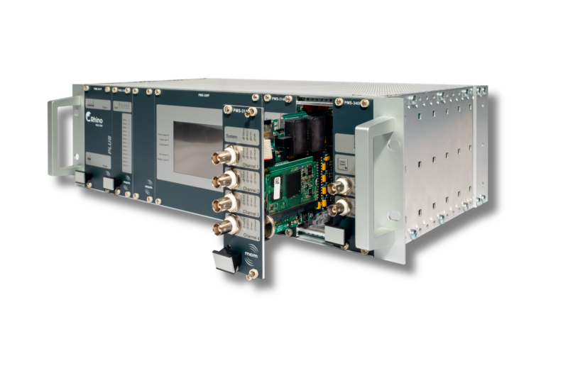
Its modular rack architecture—available in 3U and 6U formats—can be tailored to any machine configuration using a combination of functional cards. For example, the PMS-361P card handles the rack’s power supply and common relay outputs (system OK, sensor OK, alert, danger), while the PMS-341P cards provide phase-reference (tachometer) signals, digital inputs and field-bus communication. The PMS-314P cards provide dynamic channel acquisition (up to 4 channels per card) and the PMS-330P cards manage configurable alarm/trip logic and analog outputs. In the 6U configuration, the system can be equipped with dual power-supply to ensure redundant operation and uninterrupted protection in the event of a power source failure. An optional PMS-320P touchscreen display module supplies real-time visualization of system status and alarms, and front-facing BNC connectors allow access to raw signals for advanced analysis.
At the heart of the PMS-300P lies the PMS-314P acquisition card, which defines the signal-processing standard for all MC-monitoring systems. Each channel features wide input compatibility (IEPE, differential or single-ended voltage, and 4–20 mA process signals) and a measurement bandwidth from DC to 20 kHz, allowing precise capture of both slow mechanical motion and high-frequency vibration. The PMS-314P uses dual-path digital signal processing for simultaneous low- and high-frequency analysis, combined with user configurable multi-stage IIR digital filtering independent for each channel. Signals are digitized through 16-bit simultaneous sampling at up to 50 kS/s per channel, ensuring high-fidelity acquisition and accurate synchronization across all dynamic measurements. Built-in characteristic values extraction in the time domain and frequency domain such as Min, Max, Mean, Gap, Peak, Peak-peak, Smax, 1x (M&P), 2x etc. deliver processed values in real time for protection logic and condition monitoring.
By consolidating all measurements in one rack-based system, it also ensures faster commissioning and easier diagnostics throughout the machine’s lifetime. Beyond durability, the PMS-300P provides an efficient and scalable system for high-channel configurations typical of large vertical hydro generators or pump-storage machines.
Combined with the CMS-500P software, it delivers a comprehensive solution for machine protection, condition monitoring, and predictive diagnostics—offering industrial-grade performance, configuration flexibility, and optimized lifecycle cost in one system.
Diagnostics & Predictive Maintenance – CMS-500P
For large hydropower units, real-time protection alone is not enough. Long-term reliability requires a system that continuously analyzes how operating conditions evolve over time.
The CMS-500P condition monitoring software complements the PMS-300P rack system by transforming continuous sensor data into clear diagnostic and trending information. Through advanced visualization tools such as FFT analysis, orbits, waterfall plots, and airgap polar views, the CMS-500P enables maintenance teams to detect developing issues early, correlate events, and make informed maintenance decisions.
The software also supports on-site rotor balancing, guiding operators through the full procedure — from trial-weight runs to correction verification — in accordance with ISO 21940-11. Both single-plane (static) and two-plane (dynamic) balancing can be performed directly within the CMS-500P interface, helping reduce vibration levels, extend bearing life, and restore optimal running conditions.
It offers a secure client–server architecture with centralized data storage, ensuring reliable access and long-term traceability for multi-unit hydropower plants.
Recommendations for Medium Hydropower Units (10-50 MW or Medium to High Critical Units)
Medium or less critical hydropower units often operate with fewer measurement points than large or critical machines but still require reliable protection and condition monitoring to ensure availability and prevent costly shutdowns. In these installations, only the most critical components—such as bearings, shaft line, and/or generator are typically instrumented.
MC-monitoring offers two recommended scalable systems suited to these applications. Both can operate standalone or be integrated into the CMS-500P for trending and diagnostics.
Scenario #1 – Overall System Description
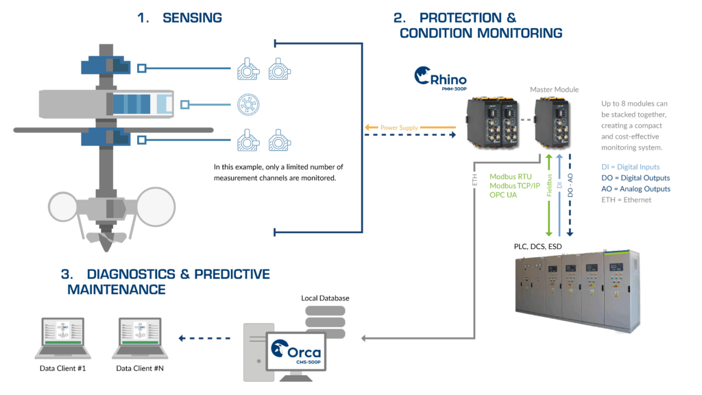
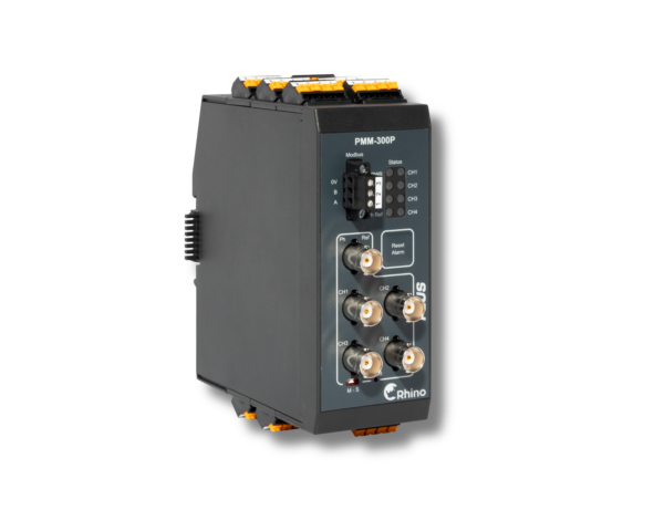
Protection & Condition Monitoring with the PMM-300P
For medium hydropower units or installations with medium-to-high operational criticality, the monitoring philosophy shifts from large centralized systems to distributed architectures that deliver full protection and condition monitoring on a smaller scale.
The PMM-300P embodies this approach — a compact, stackable module that combines the same signal acquisition and processing quality as the PMS-314P cards used in rack-based systems, but in a modular format designed for installation closer to the machine. Installed near these elements, the distributed modules significantly reduce cable lengths, lowering installation costs. Up to eight modules can be stacked together, creating a compact, scalable, and economical protection and condition monitoring system that grows with the plant’s monitoring needs. Within a stack, one module acts as the master, coordinating communication and power distribution across the connected modules. The system also allows status and alarm signals to be shared or combined between modules, ensuring consistent protection logic and centralized system awareness even in multi-module configurations.
Compared to the PMS-300P rack-based system, which is best suited for high-channel, cabinet-based installations, the distributed model offers greater flexibility and proximity to the equipment while retaining full protection capability. At the same time, it provides superior functionality and autonomy compared to the PMM-305P, which is primarily intended for cost-efficient condition monitoring.
The PMM-300P therefore represents the optimal solution for medium to high-critical hydro units, combining protection performance, compact design, and scalable architecture in a single platform.
Scenario #2 – Overall System Description
Process & Condition Monitoring with the PMM-305P
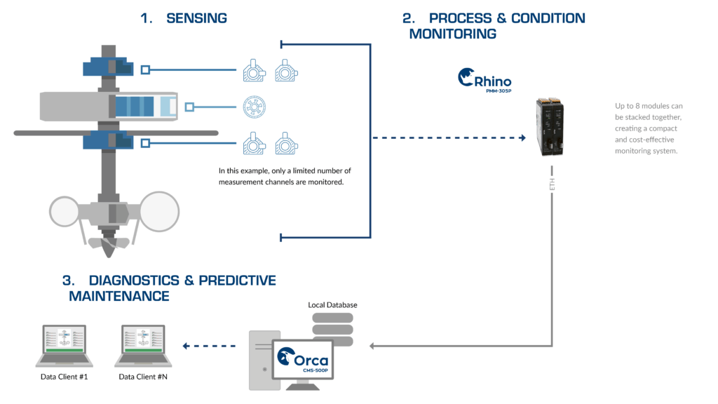
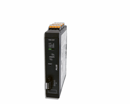
For medium hydropower units with low to medium operational criticality, the monitoring strategy often focuses on tracking equipment condition rather than implementing a full protection system. In these cases, the PMM-305P Distributed Process and Monitoring Module provides a simple, compact, and cost-effective solution to monitor the most relevant machine elements without the complexity of a centralized installation.
The PMM-305P shares the same digital acquisition technology as the PMS-314P rack card and PMM-300P module, ensuring identical measurement accuracy.
However, it is designed with a streamlined hardware concept: the module configuration is defined at the ordering stage to match the desired signal type (voltage, current, or IEPE, with integrated current excitation for IEPE sensors). This makes it ideal for retrofitting existing systems or adding monitoring points to machines that already have local protection managed by a PLC. For example, the PMM-305P can digitize the analog outputs of existing vibration transmitters, bringing legacy monitoring points into the CMS-500P environment.
While the PMM-305P offers only one digital output for general alarm signaling, it includes Modbus RTU/TCP and optional OPC UA communication interfaces for integration with the plant’s DCS or PLC systems. These interfaces transmit processed values and alarm states for supervisory control, while the CMS-500P connects via a dedicated high-speed Ethernet link to access full dynamic data for trending and diagnostics. Up to eight modules can be stacked to form a compact and economical condition monitoring system, sharing power and phase reference across modules.
Compared to the PMM-300P, which includes sensor power supply and full protection logic, the PMM-305P focuses on simplified condition monitoring for applications where downtime risk is moderate and monitoring scope is limited.
It is therefore the preferred option for cost-efficient installations or complementary monitoring systems — providing essential insight into machine behavior while keeping the architecture lightweight and easy to deploy
Recommendations for Small Hydropower Units (<10 MW or Low Critical Units)
In small hydropower installations where production capacity and operational criticality are limited, the monitoring approach focuses on essential supervision and reliability at minimal complexity.
These units generally operate with simplified control systems and fewer measurement points, where maintaining safe and stable operation takes precedence over in-depth diagnostic analysis.
MC-monitoring supports this philosophy by providing straightforward monitoring concepts that ensure dependable oversight while keeping investment and maintenance requirements low.
Overall System Description
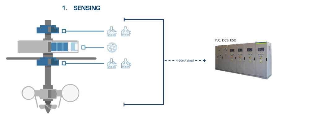
For small hydropower units or installations with low operational criticality, the monitoring philosophy prioritizes operational safety and simplicity over advanced analysis. In such applications, the objective is to maintain basic visibility of key parameters — such as bearing vibration without the need for a dedicated acquisition system.
In this configuration, the 4–20 mA analog outputs from the sensors are connected directly to the plant’s PLC or DCS. The PLC then records and supervises the live measurement values and can, if programmed, manage simple alarm or trip functions based on predefined thresholds.
This approach offers a minimalist and cost-efficient monitoring setup, ideal for small run-of-river units, auxiliary turbines, or sites with limited automation infrastructure.
Since no signal acquisition or diagnostic software is involved, this configuration does not provide advanced analysis or trending capabilities. To ensure measurement reliability over time, MC-monitoring recommends implementing a periodic sensor verification routine, during which the sensor outputs are cross-checked against reference measurements. This periodic validation ensures the accuracy of vibration or displacement readings and helps maintain system integrity with minimal intervention.
This setup can later be expanded with distributed modules for additional diagnostic capabilities without changing the core wiring.


Acquisition units & software










LET'S KEEP IN TOUCH
Sign up to receive our newsletters