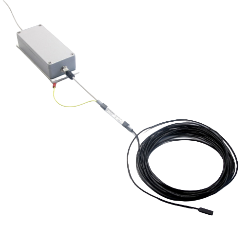
Single-axis Hall-effect transducers that measure the magnetic field in the air gap of generators, up to ±2 Tesla. Choose the MFT-100 for standard installations, or the MFT-110 when you need a probe rated to 180 °C and a digital threshold output.
Single-axis magnetic field measurement, range up to ±2 T
High accuracy, linearity (< 0.1 %) and stability (< 1 % over 10 years)
Immune to deposits and vibrations
Small, flat design for installation in small air gaps
Interchangeable sensor head
Single +24 VDC power supply
Description
The MFT-100 and MFT-110 Magnetic Field Transducers are compact, high-performance sensors based on Hall-effect technology, designed for accurate magnetic flux monitoring. Their robust construction ensures reliable operation in harsh industrial environments: the MFT-100 withstands temperatures up to 125 °C at the sensor head, and the MFT-110 probe up to 180 °C.
Each transducer can be powered by a standard +24 V DC industrial power supply. The interchangeable sensor head facilitates maintenance and minimizes downtime during replacement.
Each system consists of a flat magnetic field sensor (MFS-100 or MFS-110) and a signal conditioner (MFC-100 or MFC-110), providing a standard 4–20 mA output proportional to the measured magnetic flux density (±2 Tesla range). The MFT-110 adds an isolated digital output that switches at ±12 mT, for easier alarm integration. The outputs can be integrated into MC-monitoring’s condition monitoring software CMS-500P and/or third-party PLC/SCADA systems for real-time analysis and alarms.
Installed on the stator wall, the transducers enable continuous, real-time measurement of the magnetic field in the air gap. This online solution provides essential data on the rotor’s magnetic flux distribution and potential anomalies, and helps plant operators improve operational reliability, reduce maintenance costs and prevent unexpected outages in critical rotating machines.
Typical applications include:
Magnetic flux monitoring
Rotor pole condition assessment
Field current unbalance detection
Shorted rotor turn detection
Predictive maintenance and fault root cause analysis
Advanced analysis with CMS-500P
The CMS-500P software includes dedicated analysis features designed to process and visualize the magnetic flux data measured by the MFT.
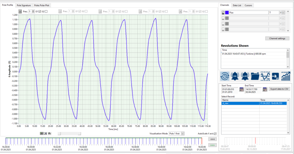
Pole Profile View
This view displays the raw magnetic flux waveform over one revolution, showing the magnetic field density measured by the MFT-100 sensor in Tesla. It allows operators to visualize the real-time flux profile generated by each rotor pole.
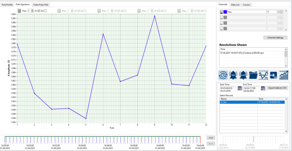
Pole Signature View
The Pole Signature provides an overview of the absolute flux values per pole, computed from the maximum amplitude of the measured magnetic field density. This view allows operators to easily verify the magnetic flux balance across the rotor and quickly identify poles with significantly lower or higher flux levels.
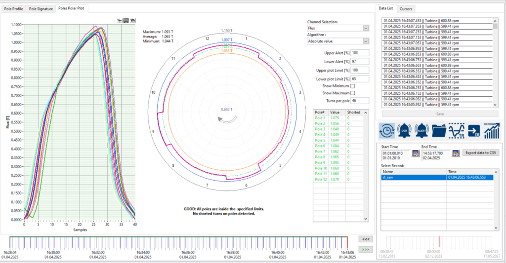
Pole Polar Plot
The Pole Polar Plot offers a circular visualization of the magnetic flux amplitude distribution around the rotor. This view simplifies fault diagnosis by clearly highlighting poles that deviate beyond defined thresholds, revealing potential anomalies such as shorted turns.
Detect Shorted Rotor Turns with the Pole Polar Plot