
MC-monitoring is proud to announce a new feature to our CMS-500P Condition Monitoring Software for Rotor Flux Monitoring: the Pole Polar Plot. This advanced visualization tool enhances the analysis of magnetic flux distribution in salient pole synchronous machines, providing operators with faster, clearer, and more flexible diagnostic insights.
In salient pole machines such as hydrogenerators and synchronous motors, ensuring balanced magnetic flux across all rotor poles is crucial to avoid electrical and mechanical stresses. Local deviations in flux amplitude may reveal underlying issues such as:
While traditional magnetic flux analysis focuses on raw flux values (Pole Profile) and absolute flux values computed from the maximum amplitude (Pole Signature), minor but critical deviations can remain unnoticed without dedicated visualization tools.
The new Pole Polar Plot view addresses this challenge by offering an intuitive, rotor-shaped visual representation of flux density variations — enabling faster and more precise diagnostics.
The Pole Polar Plot view is designed to give operators maximum visual flexibility. It allows users to analyze flux deviation based on several different calculation algorithms:
This feature simplifies fault diagnosis by providing clear indicators when specific poles deviate beyond defined limits, highlighting potential anomalies such as shorted turns.
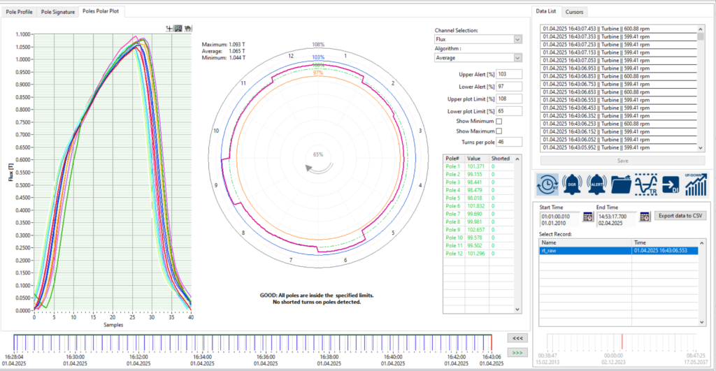
The left-hand plot displays each pole measured by the MFT-100 sensor, expressed in Tesla, over one acquisition cycle. Each peak in the waveform corresponds to the magnetic flux generated by an individual rotor pole as it passes in front of the sensor.
On the right-hand side, the Pole Polar Plot provides a circular visualization of the flux amplitude distribution around the rotor. For each pole, the radial distance represents the absolute or relative pole’s flux amplitude depending on the selected algorithm.
The circle at 100% corresponds to the average flux amplitude across all poles. The configurable Upper Alert and Lower Alert thresholds (here set at 103% and 97%) define the acceptable deviation limits.
The parameter Turns per pole (here set to 46) refers to the number of turns in each pole’s excitation winding. This reference helps estimate the potential impact of flux deviations in case of shorted turns.
In this example, all pole amplitudes are within the specified limits, indicating a balanced magnetic flux distribution and no detected anomalies.
In the following real-case example, the CMS-500P software clearly identified an abnormal magnetic flux condition indicating a potential shorted turn on the rotor.
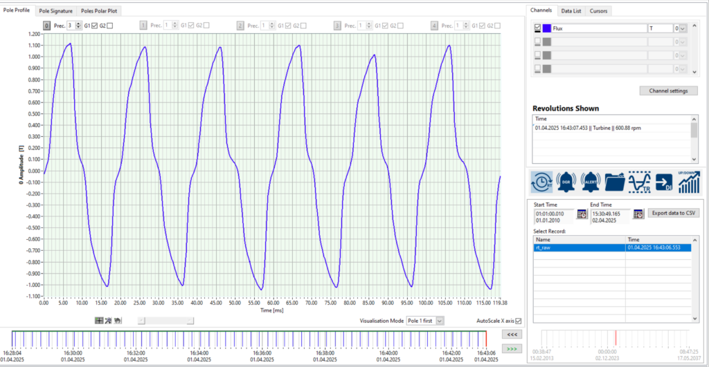
The Pole Profile View displays the raw magnetic flux waveform measured by the MFT-100 sensor, over one acquisition cycle. Each peak in the waveform corresponds to the magnetic flux generated by a rotor pole as it passes in front of the sensor. In this example, a visible reduction in the amplitude of the 9th peak can already be observed, suggesting a flux imbalance.
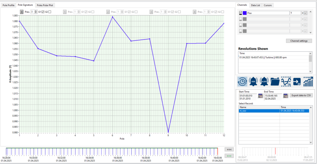
The Pole Signature View displays the absolute flux amplitude per pole. In this case, Pole 9 shows a significant drop compared to the other poles. This flux amplitude reduction is a clear signature of a potential shorted turn, as the loss of effective turns in the rotor winding leads to a measurable decrease in magnetic flux density.
The Pole Polar Plot provides an intuitive visualization of flux amplitude distribution around the rotor.
Here, Pole 9 is visibly below the configured lower alert threshold (97% of average flux amplitude), confirming a significant flux deficit.
The software automatically triggers a warning and annotates the anomaly with the message: “WARNING: Poles 9 are lower or higher than the specified limits. Potential shorted turns on poles detected.”
The Pole Flux Deviation view is part of a broader diagnostic toolkit available in the CMS-500P platform.
Operators can easily correlate magnetic flux anomalies with other condition monitoring data, including:
This cross-analysis capability enables a more accurate diagnosis by linking flux imbalance with potential mechanical or thermal root causes, providing a complete picture of machine condition.
With the addition of Pole Flux Deviation analysis, CMS-500P users can now: