
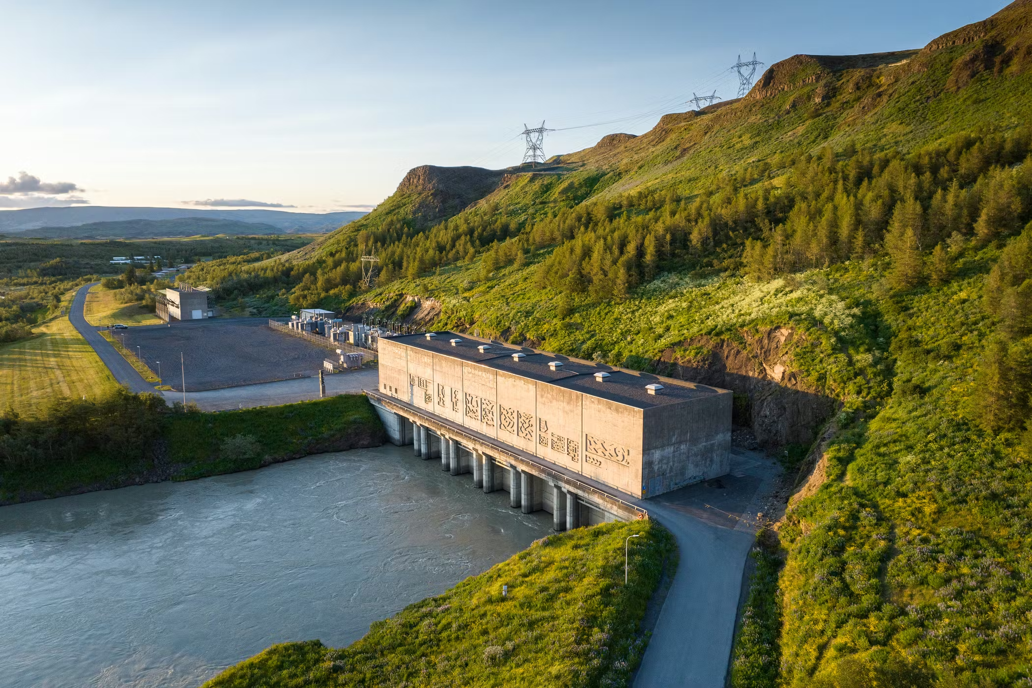

Success Story: Rotor Balancing for Hydropower: Búrfell Power Plant, Iceland
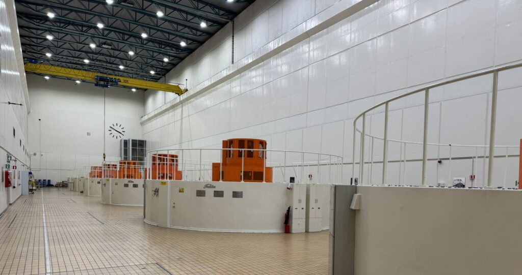
The Búrfell Hydropower Plant is one of Iceland's most important energy assets, operated by Landsvirkjun, the national power company. Located on the Þjórsá River, the plant runs six vertical Francis turbine units and plays a central role in Iceland's electricity supply. Following maintenance activities on one of its units, Landsvirkjun called upon MC-monitoring to perform an on-site rotor balancing campaign, with the goal of restoring optimal vibration levels and securing the unit's long-term operational reliability.
The objective was clear: reduce overall shaft vibration amplitudes significantly at full load, without compromising availability or requiring major disassembly.
The Challenge: Elevated Vibration on a Critical Asset
Large vertical hydro units accumulate history. Balancing weights may be installed, adjusted, or removed over decades of operation, and the resulting balance state is not always well documented. Before any corrective action can be taken, the existing condition must be fully characterised through precise vibration measurement and harmonic analysis.
At Búrfell, one of the units shaft relative vibration levels had risen significantly at the Lower Guide Bearing — the bearing closest to the turbine runner and most sensitive to rotor unbalance. The dominant vibration component was synchronous, occurring at the rotational frequency of the machine. This pattern is a strong indicator of mechanical unbalance, but confirming it and translating it into a practical correction requires both the right instrumentation and engineering judgment built from field experience.
The additional complexity here was the need to work within the constraints of an operational plant: every run-up and run-down consumes time and energy, every weight installed on the rotor must be accounted for precisely, and the strategy must adapt in real time based on how the machine actually responds — not just how the theory predicts it should.
Approach: Measurement-Driven, Adaptive Balancing Strategy
Step 1 — Establishing a vibration fingerprint
Before any weight was touched, the MC-monitoring field engineer conducted a full baseline measurement campaign. The permanently installed protection system was complemented by additional portable acquisition units, a PMM-300P for absolute bearing vibration and two PMM-305P modules connected to the existing proximity probe buffered outputs, providing a fully synchronised, multi-channel picture of shaft behaviour across all three bearing levels.
Waveform, spectrum, orbit, and 1X harmonic vector analyses confirmed a dominant static unbalance condition. The vibration energy was almost entirely concentrated in the first harmonic (synchronous) component, with consistent phase angles between bearing locations, a clear diagnostic signature that guided the entire balancing strategy.
Step 2 — Iterative balancing using CMS-500P
The balancing campaign was conducted using the integrated balancing module within the CMS-500P, MC-monitoring's condition monitoring and diagnostic software. This tool supports both single-plane and dual-plane balancing workflows, computing correction masses in real time from trial run data and presenting results through polar plot visualisation.
The campaign followed a structured single-plane balancing approach targeting the Lower Guide Bearing balancing plane, where the measured imbalance was greatest. A trial mass was first installed to characterise the machine's dynamic response, allowing the correction mass to be precisely computed. The solution mass was then applied, followed by a trim correction to further optimise the final balance state — bringing vibration levels down to the results described below.
At each stage, measurements were taken only once the machine had reached thermally stable operating conditions — a critical discipline in field balancing, where premature readings can compromise the accuracy of influence coefficient calculations and lead to suboptimal corrections. This patience, combined with a structured methodology, is what underpins a reliable balancing outcome.
Results: Measurable Vibration Reduction at Full Load
The final results, measured at full load operating conditions, showed a clear and significant improvement across all bearing locations compared to the vibration fingerprint recorded at the start of the intervention:
- ~40% reduction in relative shaft vibration at the Upper Guide Bearing
- >75% reduction in relative shaft vibration at the Lower Guide Bearing
- ~60% reduction in absolute bearing vibration velocity at the Upper Guide Bearing (measured via temporary accelerometers installed on the Upper and Lower Guide Bearing housings in both X and Y directions)
Beyond the percentage improvement, the post-balancing vibration levels were assessed against the classification zones defined in ISO 20816-5, the international standard for vibration evaluation of hydraulic power generating units, with the following outcome:
- Lower Guide Bearing: post-balancing shaft vibration in the range of 70–80 µm pp → Zone A (good — newly commissioned or recently overhauled condition)
- Upper Guide Bearing: post-balancing shaft vibration in the range of 100–120 µm pp → Zone A–B (acceptable for continuous long-term operation)
In accordance with ISO 21940-13, which governs on-site balancing procedures and references ISO 20816 as the applicable vibration acceptance criteria, the post-balancing condition of the unit is fully aligned with international recommendations for safe and reliable continuous operation.
The Turbine Guide Bearing — which was not the primary target of the balancing campaign — remained stable throughout, confirming the integrity of the overall approach.
A Field Validation of the CMS-500P Balancing Module
This project served as an important real-world validation of the balancing module embedded within the CMS-500P. Designed to integrate seamlessly with MC-monitoring's full acquisition ecosystem, the tool guided the field engineer through trial run data entry, automatic computation of correction masses, and step-by-step solution validation — all within the same software environment used for continuous condition monitoring.
The Búrfell intervention demonstrated that combining a permanently installed monitoring infrastructure an advanced software-integrated balancing tool delivers a level of diagnostic confidence and operational efficiency that conventional standalone balancing instruments cannot match. The same data platform used to identify the problem was used to solve it.
Frequently Asked Questions
What is on-site rotor balancing for hydropower turbines?
On-site rotor balancing is the process of correcting mechanical imbalance in a rotating machine — such as a hydro turbine or generator — without removing the rotor from the machine. Correction masses are calculated from vibration measurements taken during controlled trial runs and then installed directly on the rotor's balancing planes. This approach avoids the time and cost of a major overhaul while delivering significant vibration reductions.
When is rotor balancing needed on a hydroelectric unit?
Balancing is typically required when synchronous (1X) shaft vibration levels increase after maintenance activities such as runner replacement, rewind, or bearing work — or when gradual imbalance develops due to wear, erosion of the runner blades, or redistribution of existing correction weights. Continuous monitoring with shaft relative vibration proximity probes, as installed at Búrfell, allows operators to detect this trend early and plan a targeted intervention before alarm or trip thresholds are reached.
What is the difference between single-plane and dual-plane balancing?
Single-plane balancing addresses unbalance by adding a correction mass on one balancing plane, making it suitable for static unbalance conditions where the vibration is uniform along the shaft. Dual-plane balancing uses two correction planes simultaneously and can address both static and dynamic (couple) unbalance — which is more common in machines with significant axial rotor length. In practice, field engineers often start with the approach that best matches the diagnostic signature and adapt the strategy based on the machine's actual response.
How does MC-monitoring support hydropower operators with balancing services?
MC-monitoring provides end-to-end field balancing services, from initial vibration diagnosis to on-site correction and final validation. Our field engineers use the permanently installed monitoring infrastructure — including PMS-300P protection systems and proximity probes — combined with portable acquisition units and the CMS-500P balancing module to deliver precise, data-driven corrections with minimal impact on plant availability. Learn more about our engineering services.
Practical Takeaway
On-site rotor balancing delivers some of the highest ROI of any maintenance intervention available for large hydroelectric units: short execution time, no major disassembly, and results that are immediately measurable at the next machine start-up.
As hydropower operators face increasing pressure to maximize availability and extend asset life, having a monitoring infrastructure that can both detect and actively support the resolution of mechanical issues is no longer a luxury — it is a practical necessity.
We thank Landsvirkjun for their trust and collaboration, and for the opportunity to validate the new CMS-500P balancing tool under demanding real-world conditions.
LET'S KEEP IN TOUCH
Sign up to receive our newsletters