
RUNNER CLEARANCE MONITORING
Description
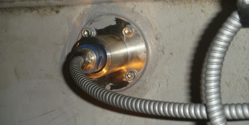
The runner blade clearance sensor measures changes in the distance between the tip of the turbine blades and the surface of the throat ring.
The surface of the turbine blade tip consists of a conductive NiCr material that absorbs the high-frequency eddy currents generated by the measuring probe in such a way as to provide an electrical signal, proportional to the air gap.
The probe itself is flush mounted on the groove ring, at the turbine centerline. It measures static and dynamic distances in the harsh hydraulic environment of large hydroelectric power plants. This monitoring is called “runner clearance” with Francis turbines, or “water gap” with Kaplan turbines.
Typical faults detections
- Off-center leading to efficiency reduction
- Turbine-to-throat ring rub
Typical installation
2 to 5 sensors uniformly installed around the throat ring, flush mounted
Monitoring parameters
- MPS: Min gap
- CMS: Blades profile and polar view
Applications

Related sensors

Acquisition systems


LET'S KEEP IN TOUCH
Sign up to receive our newsletters